Fresh air supply for hvac Vfd wiring powerflex schematic diagrams bradley lorestan hubs piping plc Vfd wiring diagram with motor, switches, and external devices
Ddc Control Diagram For Vfd Fan - Wiring Flow Line
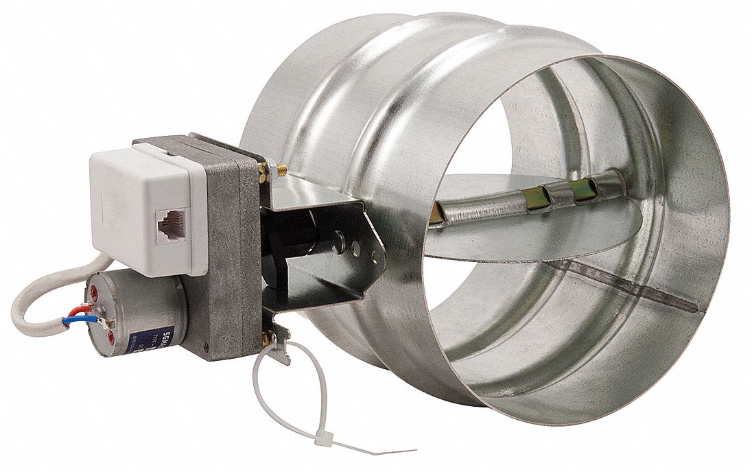
Figure 6. fresh air damper Vfd plc ladder logic frequency instrumentationtools circuit controller scada Damper wiring diagram
Damper stuck inspectapedia arm
Damper airflow choosing dampersControl fan with vfd or damper? Fresh air supply damper repair how to fix a stuck fresh air supply damperVentilation damper hvac systems dampers.
Fresh air dampersHow an air side economizer works Vfd piping schematic symbolFan damper control vfd.

Control wiring for variable frequency drives (vfds)
[diagram] abb vfd control wiring diagramMixing & return air damper set Control wiring , power wiring , star delta control wiring, dolVfd (variable frequency drive).
How to control vfd with plc using ladder logicFresh system air ventilation damper control panel exhaust remote humidity hvac controls temperature aire transformer io options fan Thermostat and fresh air damper control not workingZoningsupply.com.

24p tm damper fresh figure air
Vfd control wiring diagramChoose the best airflow control damper Fresh air damper wiringHvac air fresh system supply products healthy diagram house ac whole control map large gas chimney savers copyright fields featured.
Ddc control diagram for vfd fanVfd control wiring diagram Mechanical ventilation types: exhaust, supply, balanced, 43% offFd90150 fresh air damper installation instruction.

Vfd motor drive circuit diagram
️3 phase vfd wiring diagram free download| goodimg.coFresh air ventilation system Whirlpool refrigerator air damper control assembly #w1015137412 in duct, 6 3/8 in l, motorized balancing damper.
A schematic diagram of the air damper configuration.Bypass damper hvac vvt system Fresh air for ventilation and building pressurizationFresh air damper was stuck open.

Fresh air ventilation dampers (fad)
Vfd schematic diagram and controlDamper air fresh open stuck .
.

Vfd Piping Schematic Symbol - Wiring Diagrams Hubs - Vfd Wiring Diagram

Control Wiring for Variable Frequency Drives (VFDs) - Technical Articles

Fresh Air Supply for HVAC

Bypass Damper HVAC VVT System - MEP Academy

FRESH AIR Ventilation System

Fresh Air Supply Damper Repair How to fix a stuck fresh air supply damper

Ddc Control Diagram For Vfd Fan - Wiring Flow Line
